Triacs are important components in electronic circuits where precise control of AC power is needed.What is a Triac component?
Introduction to switching circuits and applications
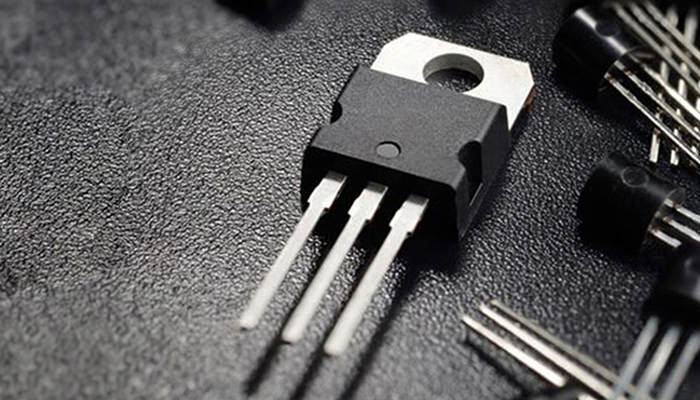
Power electronic switches such as BJTs, SCRs, IGBTs, MOSFETs and TRIACs are very important components in switching circuits such as DC-DC converters, motor speed controllers, motor drives and frequency controllers. Each device has its own unique characteristics and hence they have their own specific applications. In this article, we will learn about the TRIAC, which is a bi-directional device, which means that it can go in both directions. Due to this characteristic, the TRIAC is specifically used in situations involving sinusoidal AC power supplies.
Introduction to TRIAC
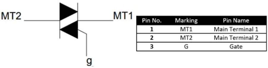
The TRIAC is a three-terminal switching device similar to an SCR (thyristor), but it conducts in both directions because it is a combination of two SCRs in anti-parallel.The symbols and pins of the TRIAC are shown below.
Since the TRIAC is a bi-directional device, when the gate terminals are triggered, current can flow either from MT1 to MT2 or from MT2 to MT1. For the TRIAC, the trigger voltage to be applied to the gate terminals can be either positive or negative with respect to terminal MT2. Therefore, this places the TRIAC in one of four modes of operation as listed below
Positive voltage at MT2 and positive pulse at the gate (quadrant 1)
Positive voltage at MT2 and negative pulse at gate (quadrant 2)
Negative voltage at MT2 and positive gate pulse (quadrant 3)
Negative voltage at MT2 and negative gate pulse (quadrant 4)
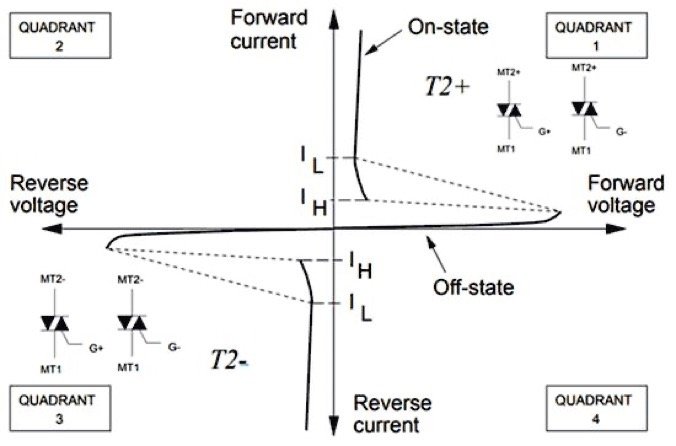
The following figure illustrates the state of the TRIAC in each quadrant.
TRIAC’s VI properties
The on and off characteristics of the TRIAC can be understood by looking at the VI characteristic diagram of the TRIAC, which is also shown above. Since the TRIAC is simply a combination of two SCRs orientated in opposite parallel directions, the VI characteristic diagram looks similar to the SCRs. as shown above, the TRIAC operates predominantly in the first and third quadrants.
Turn-on characteristics
To turn on the TRIAC, either a positive or negative gate voltage/pulse must be supplied to the gate pin of the TRIAC. When one of the two internal SCRs is triggered, the TRIAC begins to conduct depending on the polarity of the MT1 and MT2 terminals. If MT2 is positive and MT1 is negative, the first SCR turns on, and if the MT2 terminal is negative and MT1 is positive, the second SCR turns on. In this way, either SCR is always on, making the TRIAC ideal for AC applications.
The minimum voltage that must be applied to the gate pin to turn on the TRIAC is called the threshold gate voltage (V GT ), and the current generated through the gate pin is called the threshold gate current (I GT ). Once this voltage is applied to the gate pin, the TRIAC is forward biased and begins to turn on. The time it takes for the TRIAC to change from an off state to an on state is called the on time (t on ).
Like an SCR, once a TRIAC is turned on, it will remain on unless it is commutated. However, in this case, the load current through the TRIAC should be greater than or equal to the TRIAC’s latch current (I L ). Therefore, it is concluded that as long as the load current is greater than the value of the latch current, the TRIAC will remain open even after the gate pulse is removed.
Similar to the latch current, there is another important current value called the hold current. The minimum value of current that will keep the TRIAC in positive conduction mode is called the holding current (I H ). As shown in the figure above, the TRIAC will only enter continuous conduction mode after passing both the hold current and the latch current. In addition, the value of the latch current of any TRIAC will always be greater than the value of the hold current.
Turn-off characteristics
The process of turning off a TRIAC or any other power device is called commutation, and the associated circuitry used to perform the task is called a commutation circuit. The most common method used to turn off a TRIAC is to reduce the load current through the TRIAC until it falls below the value of the holding current (I H ). This type of commutation is called forced commutation in DC circuits. We will learn more about how to turn the TRIAC on and off by applying the circuit.
TRIAC Applications
The TRIAC is very commonly used where AC power must be controlled, for example, it is used in ceiling fan speed regulators, AC light bulb dimmer circuits, etc. Let’s look at a simple TRIAC switching circuit to see how it actually works.
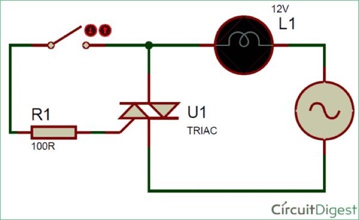
Here the TRIAC can be used to switch the AC load on and off via a button. The mains supply is then connected via the TRIAC to a small light bulb as shown in the diagram above. When the switch is closed, a phase voltage is applied to the gate pin of the TRIAC through resistor R1. If this gate voltage is higher than the gate threshold voltage, a current flows through the gate pin that will be greater than the gate threshold current.
In this case, the TRIAC goes into forward bias and load current will flow through the lamp. If the load draws enough current, the TRIAC enters a latched state. However, since this is an AC supply, the voltage reaches zero every half cycle and therefore the current reaches zero instantaneously. Therefore, latching is not possible in this circuit and as soon as the switch opens, the TRIAC closes and there is no need for a commutation circuit here.This commutation of the TRIAC is called natural commutation. Now let’s build this circuit on a breadboard using a BT136 TRIAC and check how it works.
Great care needs to be taken while using AC power supply, to be on the safe side reduce the operating voltage 230V 50Hz (in India) from the standard AC power supply using a transformer to 12V 50Hz. connect a small light bulb as a load. The completed experimental setup is shown below.
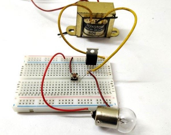
When the button is pressed, the gate pin receives the gate voltage which turns on the TRIAC. the bulb will glow as long as the button is held down. Once the button is released, the TRIAC will be in latching mode, but since the input voltage is AC, the current through the TRIAC will be lower than the holding current, so the TRIAC will turn off!
TRIAC control with microcontroller
When the TRIAC is used for dimmer or phase control applications, a microcontroller must be used to control the gate pulses supplied to the gate pins. In this case, the gate pin will also be isolated using an optocoupler. A circuit diagram of the same is shown below.
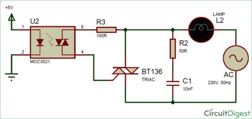
To control the TRIAC with a 5V/3.3V signal, we will use an optocoupler such as the MOC3021 which has an internal TRIAC. The TRIAC can be triggered by 5V/3.3V via a light emitting diode. Normally a PWM signal will be applied to the first pin of the MOC3021 and the frequency and duty cycle of the PWM signal will be varied to obtain the desired output. This circuit is typically used for lamp brightness control or motor speed control.
Rate Effect – Buffer Circuits
All TRIACs suffer from a problem known as rate effect. This is where the TRIAC mistakenly interrupts the voltage at terminal MT1 as a switching signal and automatically turns on when the voltage increases dramatically due to switching noise or transients or surges. This is due to the internal capacitance between terminals MT1 and MT2.
The simplest way to overcome this problem is to use a snubber circuit. In the above circuit, resistor R2 (50R) and capacitor C1 (10nF) together form an RC network that acts as a buffer circuit. This RC network will observe any peak voltage supplied to MT1.
Recoil effect
Another common problem that designers will face when using a TRIAC is the backlash effect. This problem occurs when a potentiometer is used to control the gate voltage of the TRIAC. When the POT is set to its minimum value, no voltage is applied to the gate pin, so the load is turned off. However, when the POT is set to its maximum value, the TRIAC will not turn on due to the capacitance effect between the MT1 and MT2 pins, which should find its way to the discharge path, otherwise it will not allow the TRIAC to turn on. This effect is called the backlash effect. This problem can be solved by simply introducing a resistor in series with the switching circuit to provide a discharge path for the capacitor.
Radio Frequency Interference (RFI) and TRIAC
TRIAC switching circuits are more susceptible to radio frequency interference (EFI) because when the load is switched on, the current suddenly rises from 0A to its maximum value, which creates a burst of electrical impulses that result in an RF interface. The higher the load current, the worse the interference. Using a suppressor circuit like an LC suppressor can solve this problem.
TRIAC – Restrictions
When it is necessary to switch the AC waveform in both directions, it is obvious that the TRIAC would be the first choice, as it is the only bi-directional power electronic switch. It acts like two SCRs connected back-to-back and shares the same properties. Although the following limitations must be considered when designing a circuit using the TRIAC
The TRIAC has two internal SCR structures, one that conducts in the positive half and another that conducts in the negative half. However, they do not trigger symmetrically, resulting in different positive and negative half-cycles of the output.
In addition, due to the asymmetrical switching, it can lead to high level harmonics, which can create noise in the circuit.
This harmonic problem can also lead to electromagnetic interference (EMI).
When using inductive loads, there is a high risk of inrush current flowing to the source, so make sure that the TRIAC is completely switched off and the inductive loads are safely discharged through an alternate path.
Cross reference of SCR and TRIAC from Topdiode
Topdiode produces SCR & TRIAC to replace ST, WeEn, NXP, Vishay etc & Lead time around 4 weeks. Kindly check cross reference and send RFQ for interested parts for cost down solution in free. thanks
TRIAC
| Topdiode P/N# | Package | Cross to brands | cross to P/N | Cross to package |
| F0405-6D | TO-252 | ST | T405Q-600-TR | DPAK |
| F0405-6D | TO-252 | ST | T405Q-600B-TR | DPAK |
| T0635-8A | TO-220A | ST | BTA06-800B | TO-220AB |
| T0835-6A | TO-220A | ST | BTA08-600B | TO-220AB |
| T1605-6A | TO-220A | ST | T1605G-6I | TO-220AB |
| T1635-6A | TO-220A | ST | BTA16-600B | TO-220AB |
| T2535-6M | TO-3P | ST | BTA26-600B | TOP3 Ins |
| F0810-8D | TO-252 | WeEn | BT137S-800G | SOT428 (DPAK) |
| T0210-8F | TO-220F | WeEn | BTA202X-800E | TO220F |
| T0210-8W | SOT-223 | WeEn | BTA202W-800ET | SOT223 |
| T0405-8B | TO-220B | WeEn | BTA204-800E | TO-220AB |
| T0405-8D | TO-252 | WeEn | BTA204S-800B | DPAK |
| T0405-8W | SOT-223 | WeEn | BTA204W-800C | SOT223 |
| T0435-6D | TO-252 | WeEn | BTA204S-600C | DPAK |
| T0435-6F | TO-220F | WeEn | BTA204X-600C | TO-220F |
| T0435-8B | TO-220B | WeEn | BTA204-600C | TO-220AB |
| T0635-8F | TO-220F | WeEn | BTA206X-800CT | TO-220F |
| T0835-8B | TO-220B | WeEn | BTA208-600B | TO-220-3 |
| T1235-8F | TO-220F | WeEn | BTA312X-800B | TO-220F |
| T1235-8Z | TO-263 | WeEn | BTA212-800B | SOT404 (D2PAK) |
| T1635-8A | TO-220A | WeEn | BTA316Y-800BTQ | IITO-220 |
| T4135-8M | TO-3P | WeEn | BTA41-600B | IITO3P |
| ACS108 | SOT-223 | WeEn | ACT108W-600E | SOT-223 |
| T1235-6A | TO-220A | JJM | JST12A-600CW | TO-220A |
| T2535-6A | TO-220A | JJM | JST24A-600CW | TO-220A |
| F0410-6A | TO-220A | Littelfuse | L6004L8 | TO-220L |
| F0410-6D | TO-252 | Littelfuse | L6004D8 | TO-252 |
| T1210P6A | TO-220A | Littelfuse | Q6012LH2 | TO-220AB |
| F0105-8U | TO-92 | NXP | MAC97A8 | TO-92 |
| ACS108 | SOT-223 | NXP | ACT108W-600E | SOT-223 |
** Just a few examples, we produce much more parts, send RFQ for interested parts, thanks**
Triac Price and lead time and more semiconductors consult, pls contact :carey@topdiode.hk
More to explore:www.topdiodes.com