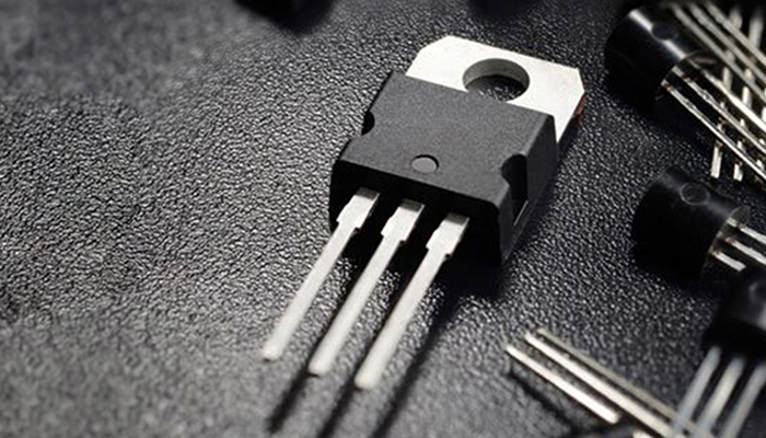
TRIAC (Triode Alternating Current) is a versatile bidirectional semiconductor switch that is widely used in AC control applications. It functions as two thyristors connected in reverse parallel with a common gate, allowing a single trigger circuit to accurately control the AC power supply
What’s TRIAC?
TRIAC is derived from the traditional thyristor. It can replace two thyristors with opposite polarity connected in parallel. In addition, it only requires one trigger circuit, making it the first choice for AC switching applications.
The origin of the term “TRIAC” involves:
TRI: Referring to Triode, derived from the first three letters.
AC: Representing AC semiconductor switch, originating from the first two letters.
These terms merge to form “TRIAC”.
Basic Characteristics
The function of a TRIAC is to combine two conventional thyristors connected in reverse parallel, and its operating principle is the same as that of a standard unidirectional thyristor.
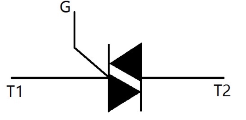
Structural Components
A TRIAC consists of two primary terminals, T1 and T2, and a gate G. The gate helps trigger the conduction of the positive and negative phases of the main electrodes, so that the symmetrical volt-ampere characteristics of the TRIAC are reflected in the initial and third quadrants.
Activation Modes
Activation can be achieved by applying a positive or negative trigger pulse to the TRIAC gate, providing four different methods of starting conduction.
Application Considerations
In actual applications, a deep understanding of its parameters ensures that the right device is selected and a customized strategy is adopted according to specific requirements.
Voltage Specifications
Choosing the withstand voltage level: The device nominal voltage is determined by the smaller value of VDRM (off-state repetitive peak voltage) and VRRM (reverse repetitive peak voltage). In calculations, the nominal voltage should ideally be two to three times the usual operating peak voltage to obtain acceptable overvoltage tolerance.
Current Calculation
In AC environments, TRIACs are described using effective current values. TRIACs used in household appliances should be rated two to three times the actual operating current, as their overload tolerance is lower than typical electromagnetic systems.
Voltage Limits
The off-state repetitive peak voltage VDRM and reverse repetitive peak voltage VRRM that a TRIAC is subjected to should not exceed the device-defined IDRM and IRRM.
Choice of On-state Voltage
For the on-state (peak) voltage VTM: This represents the transient peak voltage drop of the TRIAC at a certain multiple of the rated current. It is recommended to select a TRIAC with a lower VTM to reduce heat dissipation.
Minimum Holding Current
The holding current IH is key to maintaining the thyristor in the active state and it depends on the junction temperature. As the junction temperature increases, IH decreases accordingly.
Voltage Surge Dynamics
The voltage rise capability (dv/dt) describes the slope of the voltage increment in the non-active state and plays a vital role in avoiding accidental triggering. Exceeding this threshold may cause the thyristor to turn on unexpectedly.
Comparison between TRIAC and SCR
SCR (Silicon Controlled Rectifier) is the abbreviation of silicon controlled rectifier, which is widely used in applications where efficient regulation and conversion of electrical energy is required. Types of SCR include unidirectional, bidirectional, shut-off and light-controlled types. Its compact size and lightweight characteristics make it suitable for applications such as controlled rectifiers, voltage regulators, inverters and contactless switches.
Characteristics of SCR and TRIAC
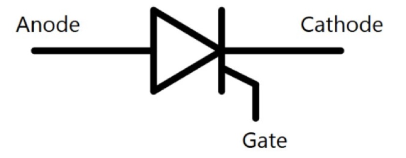
SCR: This device has three terminals – cathode (K), anode (A) and gate (G). Its working principle is to switch from off to on by an external control signal, but it will not stop until the load is removed or the voltage decreases.
TRIAC: It is equivalent to two thyristors connected in reverse parallel, with a similar three-terminal structure – one silicon anode is connected to the other silicon cathode and vice versa, defining T1 and T2 respectively, and the gate (G) is the common connection point. TRIAC can alternately conduct and turn off in both directions.
Technical composition
SCR: It is composed of four layers and three terminals in structure, which are composed of three PN junctions. It controls forward conduction by controlling the electrode current, which is different from diodes and transistors.
Bidirectional thyristor structure: The symmetrical structure of the NNPPN five-layer semiconductor is adopted. Due to the symmetry of the main electrodes, the traditional anode and cathode nomenclature is avoided. The position close to the control electrode is marked as T1, and the other positions are marked as T2.
Limitations and uses
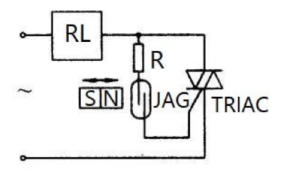
Bidirectional thyristors face challenges in voltage rise rate control because the carrier return to the off state may be delayed. Protective measures are recommended. Despite these shortcomings, bidirectional thyristors still have applications in AC control circuits, covering areas such as temperature and light regulation, explosion-proof AC switches, motor control circuits, and commutation circuits.
Uses of TRIAC
TRIACs are widely used in various fields such as industry, transportation and home appliances. Their main functions include regulating AC voltage, controlling motor speed, acting as switches, and managing systems such as automatic street lights. They are essential for tasks such as regulating temperature, dimming, and controlling stage lights.
Exploration of TRIAC Dimmer Functionality
Understanding TRIAC Dimmer Mechanics
In today’s lighting control landscape, TRIAC dimmers hold a prominent position, finding widespread adoption for their non-energy-saving capabilities. They serve a crucial role in adjusting lighting intensity in various settings.
FAQs
Q1. What is the function of a bidirectional thyristor (TRIAC)?
Answer: TRIAC is an integral component in electronic systems, with its sophisticated design making it easy to control AC power. TRIAC is able to manage a large number of voltages and currents across the AC waveform, which makes TRIAC circuits very useful in a variety of applications that require flexible power switching capabilities.
Q2. Can you describe TRIAC and its characteristics?
Answer: TRIAC contains a three-terminal AC switch, which is unique compared to other thyristor rectifiers in its bidirectional conduction capability. TRIAC remains conductive regardless of whether the gate signal is positive or negative. Therefore, it is widely used as a switch in AC systems, reflecting its adaptability in a variety of applications.
Q3. How to identify the terminals of a TRIAC?
Answer: The health of a TRIAC can be determined using a multimeter, which is an essential tool for such tasks. The state of a TRIAC can be effectively determined by setting a multimeter to a high impedance setting (e.g. 100K) and connecting the positive lead to the MT1 terminal and the negative lead to the MT2 terminal – the order of connection is flexible.
Q4. Is a TRIAC similar to a transistor?
Answer: A TRIAC is similar to a small semiconductor device, with some similarities to a diode or transistor. Made of multiple layers of semiconductor material, including an N-type material rich in free electrons and a P-type material with a large number of “holes” to accommodate electrons, TRIACs embody the essence of complex electronic design.
Q5. What is a TRIAC output?
Answer: The TRIAC Output Module (TM) has a normally open contact and is designed for 0.5 A 24 VAC loads. It is designed to effectively switch 24 VAC control circuit loads commonly found in standard HVAC systems, as well as 24 VAC dual position or floating actuators. Sold conveniently in packs of 10, these modules are designed to meet the varying needs of a variety of systems.
For further question or inquiries, please kindly contact Loie: sales4@topdiode.com, or visit our website: www.topdiodes.com